
How to Confirm a Billiard Slate Drawing: What to Check Before the Machine Starts
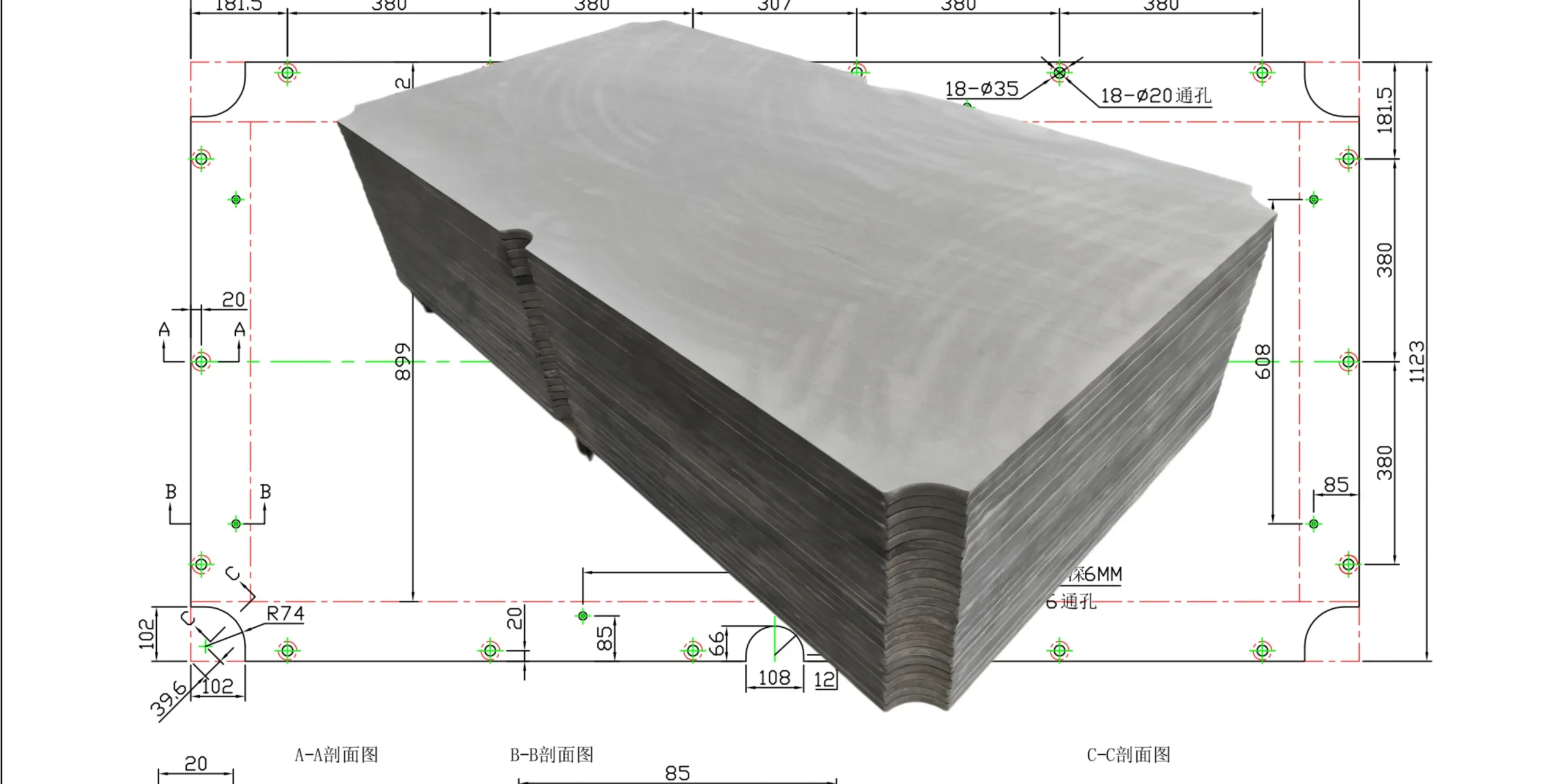
Before CNC machining begins, a billiard slate drawing must be checked for dimensional accuracy, machining requirements, and compatibility with the table frame, cushions, and mounting hardware.
A drawing can show the correct overall dimensions and still contain errors in pocket openings, hole positions, seam locations or panel thickness. Found after machining, those errors mean costly rework, delayed assembly — or slate that simply does not fit the intended table. A slate can be machined accurately to the wrong drawing: the outline can be flawless and still be the wrong outline; the holes can be drilled cleanly and still sit in the wrong places.
In a slate workshop, nobody reads a whole drawing. A CNC programmer reads the geometry. An inspector reads the acceptance numbers. An installer — usually at your end — reads the interfaces. Three readings, three directions, each blind to the other two. A drawing is confirmed when all three readers can finish their job from the paper alone, without inventing a number.
This guide explains how to review a billiard slate CAD drawing, confirm critical dimensions and tolerances, resolve missing information, and approve the final production drawing. It is written for table manufacturers, OEM buyers, importers and engineers sourcing custom snooker slate, pool table slate or other billiard slate configurations. If the order information is still being assembled, the six production fields are walked through in Information Required for Custom Production; the pocket-specific confirmation process has its own page in CNC Pocket Cuts and Drawing Confirmation, which follows one machined feature in detail. The goal is simple: the buyer and the manufacturer agree on the same complete, measurable drawing before production begins.
Quick answer — a drawing is confirmed when three readers can each do their job from it:
The programmer — geometry: finished panel dimensions, piece layout and joints, hole coordinates, pocket references, datum edges, units, revision.
The inspector — acceptance: thickness and its permitted band, tolerance per critical feature, flatness scope and method, surface condition.
The installer — interfaces: frame support and bolt alignment, cushion and pocket interfaces, clearance for hardware.
Approve when all three readings end without a question mark. A revision number is cheaper than a re-cut panel.
Reading Zero: The Sheet Itself
Before anyone checks a dimension, confirm which document is under discussion. A custom project accumulates drawings: your original CAD, a revised version after a change, the factory's production drawing built from your geometry, the final sheet released for machining. To the eye they can be near-identical. To the shop floor they are different documents, and only one of them was ever approved.
The check happens in the corner of the sheet, where the title block lives:
| Title-block line | What it has to settle |
|---|---|
| Drawing number | A unique reference both sides can name in one line |
| Revision | The latest revision both parties agreed — and which earlier version it replaces |
| Table model | The model or project the sheet belongs to |
| Slate configuration | Number of pieces and their arrangement |
| Units | Millimetres or inches, stated on the sheet |
| Date | The date of the current revision |
| Approval status | Whether this revision is released for production |
| Customer reference | The purchase order, project or model number it travels with |
A drawing does not become approved by being emailed, uploaded or discussed. It becomes approved when someone records that this revision is the manufacturing reference for this order. Until that record exists, everything after it — the geometry checks, the tolerance notes, the release checklist at the end of this page — is being performed on a document that could still be replaced.
Two habits prevent most version accidents. Give every released revision a clean label — Rev. A, Rev. B — and name the revision it replaces. And when a drawing travels as both CAD and PDF, treat them as one document: the PDF is what gets read and approved, the CAD file is what gets measured and programmed, and neither may quietly disagree with the other. In a well-run slate workshop, the released sheet is printed and posted where the machine operator reads it, and the work order names the revision — small disciplines, but they exist because the alternative has a price. For how a single machined feature travels through its own version history, the pocket drawing in particular, the detailed process is on our CNC pocket cuts and drawing confirmation page.
Units belong in Reading Zero because they are identity, not geometry. Most drawings in this trade arrive in millimetres, but design offices on both systems send us sheets, and a number copied without its unit is a coin toss. If a project mixes drawings from different countries or suppliers, confirm the unit on the sheet before comparing anything on it.
The Programmer's Reading: Geometry That Answers for Itself
The programmer is the first reader who has to act on the drawing. Their job is to turn lines into machine motion, and machine motion does not handle ambiguity, intent or context — only numbers attached to positions. Every question the geometry cannot answer from the sheet becomes a phone call, an assumption or a wait.

Start with the outline. Are the dimensions on the sheet the finished slate dimensions, or the nominal dimensions of the table? The two are easy to conflate on a busy drawing: a 9 ft designation belongs to the table, not to the stone, and two tables in the same size class can carry different slate outlines. Confirm that the numbers describe the stone, that they are taken from its external edges, and whether each figure belongs to a single panel or to the assembled bed.
On a multi-piece bed, the assembled outline is not enough information: every panel has to be right individually. A three-piece pool slate needs each of its three sections dimensioned on its own, because the total can be correct while the centre panel is not. A five-piece snooker bed needs all five sections dimensioned and oriented, and no two five-piece layouts should be assumed identical: different table models slice the bed differently. If the panels are meant to be installed in an order — head, centre, foot — that order belongs on the sheet. Joint positions deserve the same respect: if a joint position conflicts with the frame's support design, that has to be resolved before production — some table designs provide dedicated seam supports, and the drawing should show which arrangement it expects. How joint faces are actually machined is a separate subject, covered in slate edge and joint machining.
Then the positions. A hole or a pocket cutout can be located on a drawing in two ways: from a named datum edge, or by chaining measurements from the previous feature. Both look precise. Only one is safe. In a chain, every position inherits the errors of everything before it — a small drift in the first step arrives at the last hole magnified — and if the workshop happens to measure from the other end of the chain, the drawing gets built backwards. Two people can read the same number honestly and still build two different slates. The difference is not arithmetic; it is which edge they started from. A confirmed drawing names its datum edges and dimensions every critical position from them. Errors in a chain travel; errors from a datum stay home.
Pocket openings get one paragraph here, not a section, because their geometry has its own pages. The review question is only whether the pocket information is complete and unambiguous: for tables with pocket openings, every opening dimensioned from defined reference points; symmetry accepted only when the design states it explicitly — through a symmetry note or dimensioning that makes it unambiguous — never assumed from a drawing convention; and any difference between the left and right of the bed dimensioned rather than implied. The full confirmation workflow for pocket cuts — including what happens when an opening crosses a joint — is in CNC pocket cuts and drawing confirmation, and the machining side of the geometry is in pocket opening machining.
The Holes: One Feature, Read Twice
Holes are worth their own heading for two reasons: both other readers need them — the programmer needs their position, the installer needs their purpose — and they are where drawings most often rely on assumption. A hole can have the correct diameter and still be in the wrong place.
Check each hole against the drawing for: diameter and any countersink or counterbore; position, ideally coordinates from the named datum edges rather than a chain of distances; quantity and arrangement; through or blind, where the design distinguishes them; and any clearance the frame or hardware requires around them.

The second reading is the one that gets skipped. Not every hole on a table drawing belongs to the slate — some mounting details live in the frame or rail system, and the slate's job is only to carry the ones it truly needs. Before release, the drawing should state which holes and cutouts are machined into the slate, and features that belong elsewhere should be removed from the sheet rather than left for interpretation. A hole whose purpose or position is unclear is a question for the clarification loop, not a decision for the shop floor. How hole layouts are specified and machined — diameters, depths and patterns — belongs to CNC drilling and mounting holes; this page's question is only which holes belong to the slate and where. For the US market, where hole patterns follow particular table conventions, the layouts are summarised in our American pool table slate buying guide.
The Inspector's Reading: Numbers That Can Be Checked
The inspector never reads the drawing to build anything. They read it to decide what passing means — and that only works if the sheet carries numbers that can be measured, against a method that was agreed. Which is why "high precision", "perfectly flat" and "accurate machining" have no place on a production drawing: they are intentions, and intentions cannot be inspected. A confirmed drawing states what is measured, over what area, with what tolerance, and what counts as inside.
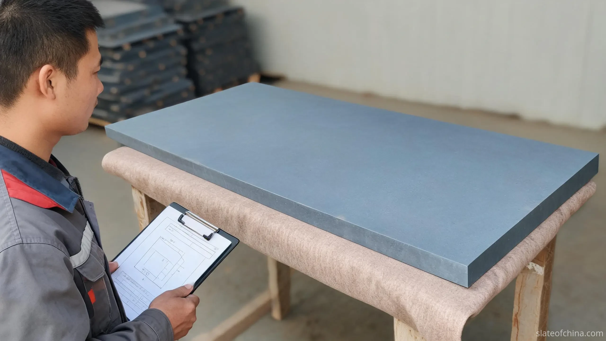
Thickness is the first number. The nominal figure — 25 mm, 38 mm, 45 mm, whatever the design calls for — is not a specification on its own. The reading confirms the required finished thickness; the permitted band around it, if your engineering sets one; whether every panel follows the same thickness specification; any local steps, recesses or rebates; and which faces the measurement is taken between. If your own QC standard exists, attach it; if it does not, ask the factory to state its standard in writing and attach that instead — the same three routes for tolerances described on the custom production information page.
Thickness and flatness are different requirements, and the drawing should treat them that way. Thickness is the distance between two faces; flatness is how far a surface may wander from a true plane. A panel can pass one and fail the other. For flatness, the scope matters as much as the number: the requirement can apply to one panel, to each panel separately, or to the assembled bed after installation — three different specifications, not three ways of saying one. The assembled surface depends on things no single panel controls: joint preparation, support, leveling. How flatness is actually measured when panels arrive has its own page on checking billiard slate flatness on incoming inspection, and the seam side of the assembled surface belongs to slate joint and seam installation.
Tolerances belong on features, not on drawings as a whole. Overall dimensions, thickness, hole positions, pocket cutouts and joint positions each carry their own practical limits, and a drawing that assigns one blanket tolerance to everything has usually not been read by anyone. The rule we work to is simple: if a characteristic can get a panel rejected when it drifts outside a limit, the drawing says how it is checked and what acceptance looks like — and the inspection scope, full or sampling, is agreed per order rather than assumed. The same discipline applies to surface condition: "polished" and "smooth" describe a mood, not a finishing state, and billiard slate carries application-specific surface expectations that should be named rather than implied. The general specification landscape is summarised in our billiard slate technical specifications overview.
The Installer's Reading: The Interfaces the Drawing Must Respect
The third reader never opens the CAD file. The installer meets the slate as a physical object that has to sit on a frame, under cushions, inside pocket hardware — and every interface in that sentence was decided somewhere else, on a different document. The installer's reading asks one question of your slate drawing: does it agree with those other documents?
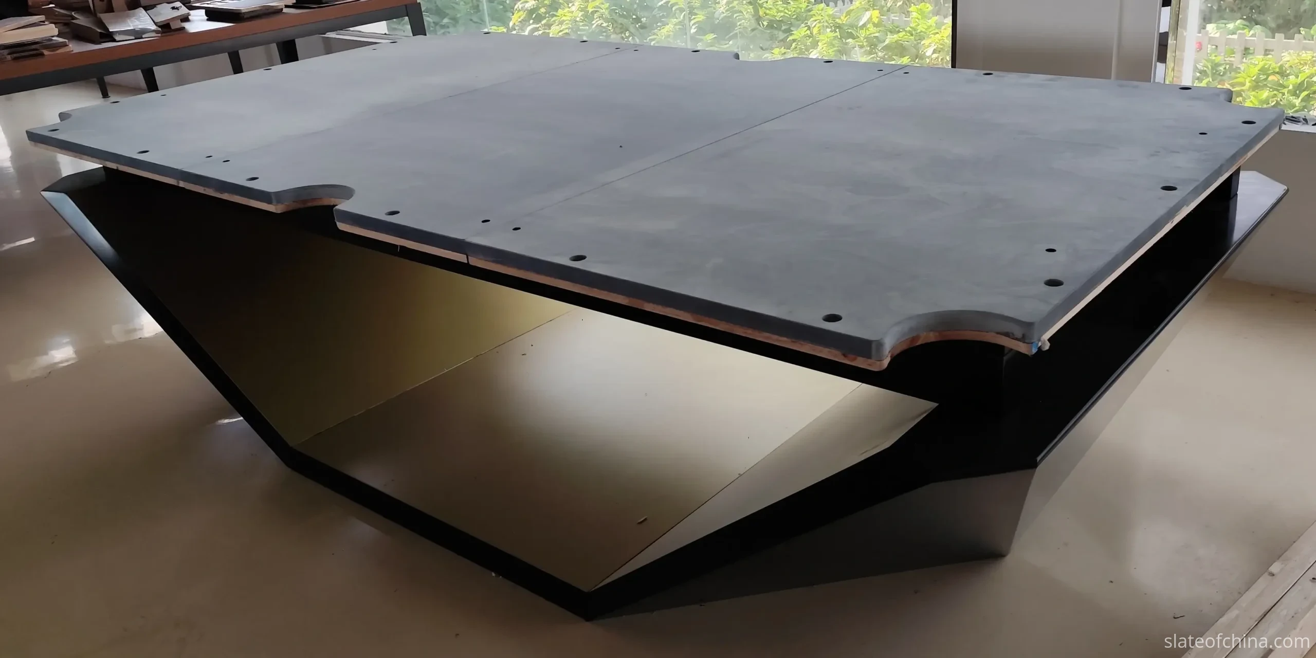
The classic failure is not a wrong dimension but a lonely one. The slate's external dimensions do not define the playing area; the nominal table size does not define the slate; the cushion nose, the cushion facing, the pocket opening and the slate cutout are four different reference geometries that have to be reconciled by design, not by hope. A slate drawing that has never been compared with the frame drawing is two documents guessing about each other.
| Interface | What has to agree |
|---|---|
| Frame support area | Every slate edge and every joint lands on structure the frame actually provides |
| Bolt pattern | Slate hole positions match the frame's bolt positions — same datum, same side |
| Pocket assembly | Slate cutouts match the pocket hardware and cushion geometry of the design |
| Rail height and hardware | Panel thickness leaves the rail system its designed clearances |
| Frame rebate and edge details | Any stepped or rebated edge profile matches the frame's mating detail |
For OEM projects the habit is structural: verify the slate drawing against the table manufacturer's approved design — the current one, at its current revision — rather than reconstructing the slate from nominal table dimensions. When beds repeat across seasons, the same drawing control that keeps one order honest keeps a whole programme honest; how we hold that consistency across repeat batches is described in OEM billiard slate for table manufacturers.
What No Reader Should Have to Infer
Most drawing problems reach a factory dressed as shortcuts. The words are friendly; the assumptions underneath are not. Each row of the table below is a real sentence from real inquiries, and each one silently asks the factory to decide something only the table design can decide.
| The sentence | What it silently assumes | What confirms it instead |
|---|---|---|
| "It's a 9 ft table, you know the sizes." | Every 9 ft design shares one slate outline | The confirmed table design or the frame drawing |
| "Standard pockets." | One universal pocket layout exists | Each opening dimensioned from its reference points |
| "Same as the last order for this model." | The earlier revision is still the current one | The current drawing, under its own revision number |
| "I'll send a photo of the old slate." | Photographs carry geometry | Measured dimensions or a dimensioned sketch — perspective distorts and hides edges |
| "Holes as usual for this style." | The factory knows which holes belong to the slate | A hole schedule with datum coordinates and diameters |
An inferred dimension is still a decision — just one made by whoever did the guessing. Keeping those decisions with the person who knows the table is the entire point of a drawing review.
When the Drawing Has to Be Rebuilt
Not every project starts with a CAD file. Some begin with an existing table and no surviving documentation; some inherit an old drawing nobody can vouch for. In those cases the drawing can be rebuilt from physical references: a verified original slate, a complete set of measured panel dimensions, a full-size template, a confirmed frame drawing, or a previously approved sample.
A physical reference is a starting point, not an authority. An old slate may have been modified, repaired, or made to an earlier specification than the table it came from. Measurements taken on an installed bed fight access, joints and hardware. Photographs explain a design wonderfully and dimension it not at all. If a sample is used, record which dimensions were verified and which still need confirmation. The full measuring method for rebuilding a drawing from an existing bed is the subject of Replacement Slate for Existing Billiard Tables.
The Clarification Loop
When the review finds a gap — an undimensioned opening, two overall widths that disagree, a hole with no stated purpose — the finding goes into a loop, and the loop has a shape:

- Identify the feature by its drawing reference or its location on the sheet.
- Describe the problem in writing, not on a call.
- Supply the missing dimension, tolerance or design instruction.
- Issue the revised sheet under a new revision, replacing the one it supersedes.
- Circulate it to everyone who held the old version, and confirm the final revision before machining — not after.
The writing matters more than it sounds. A dimension settled by phone call lives in two memories; a dimension settled on a revised sheet lives in one document. And when a factory runs several table models for the same customer, each model's approved drawing stays separate and clearly identified — dimensions from one model applied to another is the accident that approval discipline is designed to make impossible.
Who decides what stays stable through the whole loop: the factory may flag, question and prepare its production drawing, but design intent — what the table is, what fits what — stays with the customer. A focused clarification process helps reduce unnecessary review rounds: each question identifies the specific feature, explains what remains unclear, and states what is needed before production can proceed.
What Approval Actually Authorises
Approval is not a mood and it is not a courtesy. When you approve a drawing you are doing three specific things: accepting this revision — this one, by number — as the manufacturing reference for this order; authorising the factory to machine to it; and fixing the benchmark the finished slate will be inspected against. "Looks good, please proceed" does none of that. A proper approval names the drawing number, the revision, and the order it belongs to.
Approval also changes what happens to questions. Before release, an unclear dimension is a clarification; after release, the same dimension is a change. Changes are still possible — but they travel as a new revision, with their impact on machining work, cost and delivery time assessed before production continues, and the further the order has progressed, the narrower the options. A revision after approval is not an embarrassment; it is a priced event. An unannounced change is the accident.
None of this removes production quality control — it defines it. The approved drawing is what finished panels get measured against; without it, passing has no meaning. What you as a buyer should hold in your own hands at inspection time is a separate subject, covered in billiard slate quality control: what buyers should check.
Example of a Written Drawing Approval
A workable approval can be one sentence, with the blanks completed before it is sent:
The drawing number, the revision and the order reference are completed before the approval goes out, and any unresolved technical questions are settled before release. That is the whole ceremony: the approval names what it authorises, and nothing else.
Frequently Asked Questions About Confirming a Billiard Slate Drawing
What file format should a billiard slate drawing be sent in?
A dimensioned PDF is the working reference for review and approval, and a CAD file such as DWG or DXF gives the factory exact geometry for manufacturing preparation. Many projects run with both, provided the two files show the same revision. Whichever format is used, the released revision should be named so the workshop and the approval point to the same sheet.
Can a billiard slate be machined from a PDF drawing alone?
It depends on how complete the PDF is. A fully dimensioned drawing can carry a straightforward design on its own, while complex pocket openings, hole patterns or special profiles may need CAD data or written clarification. A drawing review before production exists precisely to show which case you are in before the machine is booked.
Why can't the slate dimensions be calculated from the nominal table size?
Because a nominal size is a class of table, not a set of dimensions. Two tables described as 9 ft can carry different slate outlines depending on the frame, the cushion construction and the playing-area design. The finished slate dimensions have to come from the confirmed table design, a verified drawing or measured reference panels — never from the size name alone.
Is a thickness tolerance the same thing as a flatness tolerance?
No. Thickness tolerance defines the acceptable variation between the two faces of a panel. Flatness tolerance controls how far a surface may deviate from a true plane. A panel can pass one requirement and fail the other, so the two are specified and inspected separately.
Can the slate factory correct or complete my CAD drawing?
The factory can flag missing information, ask for clarification and prepare its own production drawing from your geometry. What it cannot take over is design intent: decisions affecting the frame, cushions, playing area or hardware are confirmed with the customer before machining. An incomplete CAD file is a normal starting point, not a problem — it just means the clarification loop runs before release.
What should a written drawing approval actually say?
At minimum, three things: the drawing number, the revision being approved, and the order or model it applies to. 'Looks good, please proceed' is a comment, not an approval. A proper approval states that the named revision is accepted as the manufacturing reference for the specified order.
Can the drawing be changed after it has been approved?
Yes — changes are normal, but they travel as a new revision, with the impact on machining work, cost and delivery time assessed before production continues. The further the order has progressed, the narrower the options become, which is why open questions are resolved before release rather than after it.
The Pre-Release Checklist
Everything above compresses into one table. Five areas decide a release — dimensions, geometry, interfaces, tolerances, revision control — and the checklist walks them in the order the readers meet them. Approve the geometry, not just the picture: a rendering can look right and still hide an undimensioned pocket or a hole pattern with no datum. Not every order needs every row; every production-critical requirement needs one of them.
| Checkpoint | What confirmation looks like |
|---|---|
| Sheet identity | Drawing number, revision and model named; the replaced revision identified |
| Units and datums | Millimetres or inches stated; datum edges named; critical positions dimensioned from them |
| Assembly outline | Finished overall dimensions, taken from external edges, confirmed as slate dimensions |
| Panel dimensions | Every panel dimensioned individually, with its orientation marked |
| Configuration | Piece count and arrangement match the table design |
| Thickness | Finished thickness stated, with the permitted band or the factory's written standard attached |
| Feature tolerances | Critical features carry their own limits, and the inspection scope is agreed |
| Joints | Positions and contact edges confirmed against the frame's support |
| Pocket geometry | Every opening dimensioned; differences dimensioned, symmetry not assumed |
| Holes | Coordinates, diameters and purpose confirmed as belonging to the slate |
| Interfaces | Sheet checked against the frame and cushion design; CAD file and PDF agree |
| Release | Open questions resolved; approval recorded against the named revision |
What travels with the drawing makes the review faster: the CAD file in an agreed format such as DWG or DXF, the dimensioned PDF for approval, the table frame or interface drawing where one exists, your QC standard or inspection requirements, and — if the project is based on an existing table — a note saying whether the geometry has been verified against it. The six production fields that frame the whole order are assembled on the Information Required for Custom Production page, and if a bed like this has not been quoted yet, the same confirmed sheet produces the price — the five inputs that make a quotation fast are on How to Request a Billiard Slate Quotation. The wider sourcing journey, from supplier checks to import documents, is mapped in the billiard slate guide.
Need a Billiard Slate Drawing Reviewed Before Production?
Send your CAD file or dimensioned PDF together with the table model, required slate thickness, number of slate pieces and any critical machining requirements. If available, include the table frame drawing or mounting specifications — the interfaces the slate has to respect are often on that sheet rather than the slate drawing. Our team can review the supplied information, identify missing dimensions or unclear machining details, and discuss the next steps before production begins.
Send Your Drawing for Review · Custom Machining from Customer Drawings