
CNC Pocket Cuts and Drawing Confirmation: Why the Drawing Decides the Pocket
The Evidence Chain Before the Tool Moves
- Source — every pocket dimension has to come from somewhere. A guess is not a source.
- Drawing — the dimensions are written down, not described over the phone. "Standard pocket" is a request, not a specification.
- Review — the drawing is checked against the table design before CNC. The review bench is cheaper than the rework bench.
- Approval — one identified revision is frozen as the production reference. Not five email attachments — one.
- Cut — the tool follows the approved drawing. The cut is irreversible; the drawing is not.
"We need slate for a 9 ft pool table, standard pockets."
That is how the email usually starts. We write back and ask for a drawing. The buyer replies, sometimes a little impatiently: It's a standard pool table. Why do you need a drawing?
I have answered that question more times than I have answered any other question in this job, and the answer is always the same: because there is no such thing as a standard pocket. There are pool tables, and there are snooker tables, and there are Chinese 8-ball tables, and within each of those there are brands, and within each brand there are models, and the pocket geometry on one model is not guaranteed to match the pocket geometry on the next. A 9-foot pool table from one manufacturer and a 9-foot pool table from another can have different pocket openings, different corner radii, different pocket-centre positions, and different relationships between the pocket and the slate edge. The table size tells us the category. The drawing tells us what to cut.
This page is about what happens between the email and the CNC machine — the part that is easy to skip and expensive to skip badly. It is not about how the pocket is machined once the drawing is approved (that is covered in the pocket opening machining page), and it is not about the mounting holes that fasten the slate to the frame (that is covered in the CNC drilling and mounting holes page). It is about the drawing itself: why we ask for it, what it has to show, how we confirm it, and what happens when it is missing.
The Golden Rule
Never machine a custom billiard slate pocket from a table size or verbal description alone. For OEM production, the approved drawing is the controlling document — not the table name, not a photo, not a memory of a previous order. Pocket machining is not simply cutting a hole; it is interpreting an approved drawing and reproducing its geometry accurately in stone.
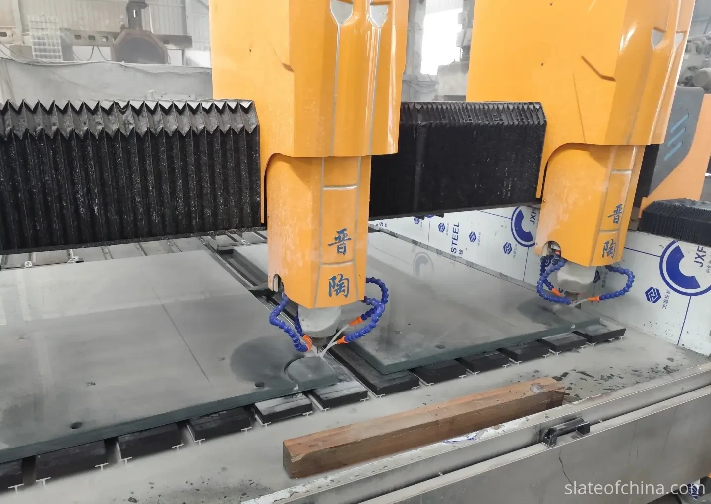
Where Every Pocket Dimension Has to Come From
Before a pocket is cut into a slate, every dimension of that pocket has to come from somewhere. That sounds obvious, but in practice it is the single most common point of failure in custom billiard slate production: a dimension appears on the CNC programme, and nobody can say where it came from.
The pocket opening has a width, a depth, a shape, a corner radius, a centre position measured from a reference edge, and a relationship to the adjoining pocket and the slate joint. Each of those is a separate decision, and each has to be traceable to a source. The source can be a CAD drawing, a dimensioned technical drawing, an approved sample, or a reverse-engineered template — but it has to be a source, not an assumption. When the operator asks where did this radius come from? and the answer is I think the customer said something about 12 mm on the phone, the evidence chain is broken. The dimension might be right, but it cannot be verified, and a dimension that cannot be verified should not be cut into stone.
This is the principle that runs through the rest of this page: every pocket dimension has to have a documented source, and before CNC machining that source has to be captured or confirmed in the approved production drawing. The source may begin as a sample, a template or a set of measurements — but by the time the tool moves, it has to be a dimension on an approved drawing, not a table name, not a photograph, not a memory of a previous order. If the drawing does not state the dimension, the dimension has to be confirmed and added before production. The pocket opening machining page covers what happens to each dimension once it is translated into the CNC programme; this page covers how those dimensions are established and confirmed before that translation begins — the drawing-confirmation stage of billiard slate pocket machining.
What a Pocket Drawing Has to Show
A useful pocket drawing does not have to be complicated, but it has to be complete. "Complete" means that someone standing at the CNC machine with only the drawing in hand can machine the pocket without asking a single additional question. If they would have to ask how wide is the opening? or where is the centre? or is this corner sharp or rounded?, the drawing is not yet complete.
In our production process, a pocket drawing has to show five things.
The opening dimensions. The width of the pocket mouth, the length or depth of the opening, and — where the design uses a circular or partially circular opening — the diameter. The dimensions have to refer to clearly defined locations: the pocket mouth at the cushion line, the pocket throat, the underside opening, and so on. A single number labelled "pocket opening" is rarely enough, because a pocket has several widths depending on where you measure it.
The pocket centre positions. The position of each pocket is just as critical as its size, and it has to be established from a reliable reference. The drawing should make it possible to determine the distance from a defined datum — usually a slate edge or a playing-area corner — to the centre of each pocket. For a six-pocket table, that means six centre positions, each measured from the same reference system. "Centred on the edge" is not a position; "135 mm from the left edge, on the centreline of the long side" is a position.
The pocket shape. Not every pocket is a simple rectangle or circle. Depending on the table design, the opening may include angled sides, curved transitions, a stepped underside, or different geometries for corner and side pockets. If the shape is not a plain rectangle, a CAD profile is much safer than a verbal description — because the verbal description can be read two ways by two people, and only one of them is cutting the stone.
The corner radius. If the pocket has rounded corners, the radius has to be stated. A drawing that shows a rounded corner without a radius value leaves the radius to the manufacturer, and the manufacturer should not select a radius based on a different table. If the radius is not specified, we ask. We do not assume.
The tolerances. Not every project needs tight tolerances, and the appropriate tolerance depends on what the pocket interfaces with — the cushion, the liner, the facing, the leather pocket. But if a tolerance matters for the assembly, it should be on the drawing: the opening tolerance, the position tolerance, the radius tolerance. A drawing without tolerances is workable for a prototype; a drawing with tolerances is workable for a production run.
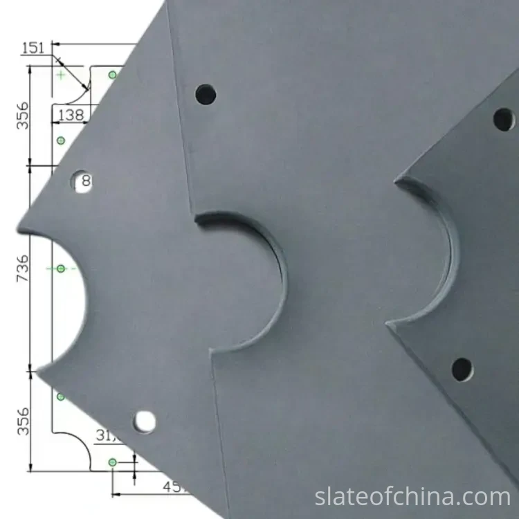
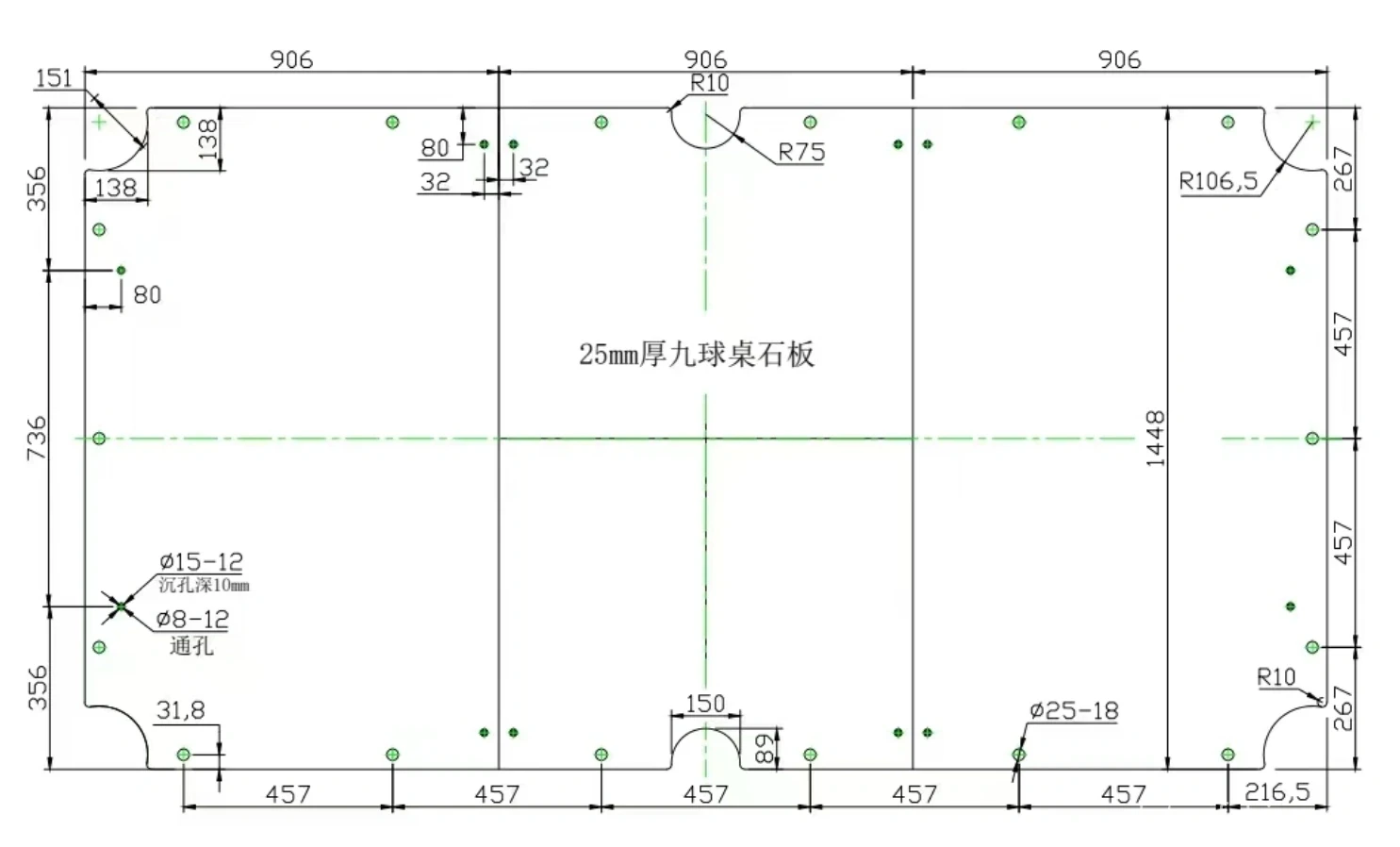
The drawing below is a real production drawing for a 9 ft pool table slate. It shows exactly the kind of information a CNC operator needs: the slate outline, the six pocket positions (four corners + two side pockets), the opening dimensions, the corner radii, the mounting-hole specifications, and the datum edges from which everything is measured.
Why the Table Name Is Not the Drawing
"9 ft pool table" is the phrase we hear most often in inquiries, and it is a perfectly good phrase — for identifying the category of table. It tells us the approximate playing area, the general scale of the slate, and the family of hardware that might be involved. What it does not tell us is anything that the CNC machine needs to know.
The machine does not cut a "9 ft pool table." It cuts a specific opening at a specific position on a specific panel, and the specificity has to come from somewhere. Table size is identification information. A drawing is manufacturing information. The two are not interchangeable, and treating the first as if it were the second is the shortest route to a rework order.
When a buyer tells us "9 ft pool table," the following may still be completely unknown: the exact slate dimensions, the playing-area dimensions, the pocket opening size, the pocket centre location, the corner radius, the pocket shape, the cushion system, the rail construction, and the mounting-hole locations. Every one of those is a dimension the CNC programme needs, and every one of them has to come from the drawing — not from the table name.
This is why we treat the table size as the first line of the inquiry and the drawing as the first requirement of the production. The comparison of pool, snooker and Chinese 8-ball slate covers the differences between table types; this page covers why knowing the type is not the same as knowing the geometry.
What Happens When No Drawing Reaches the Machine
The most serious problem with machining a pocket without a confirmed drawing is not that the pocket will look obviously wrong. It usually looks fine. The problem is that it may look correct and still fail to match the component it was cut for.
A pocket that is 3 mm too wide still looks like a pocket. A pocket whose centre is shifted 5 mm from the designed position still looks like a pocket. But when the cushion arrives, or the pocket liner, or the rail bracket, the mismatch appears — and by then the slate has been cut, the pocket geometry cannot be uncut, and the correction is either a rework or a remake. The review bench is cheaper than the rework bench, and the rework bench is cheaper than the remake.
An incorrect pocket position can affect cushion installation, rail alignment, pocket-liner fitting, pocket-bracket location, table-cabinet assembly, and the final playing-area dimensions. None of those problems is visible when the pocket is being cut. They appear later, at assembly, when the slate meets the rest of the table — and the cost of fixing them has multiplied by the number of components that were built around the assumption that the slate would be correct.
A customer may say: "9 ft pool table, standard pockets." That sounds clear, but it is not a complete machining instruction. The manufacturer may still need to know: which pocket profile? What opening size? What corner radius? Where is the pocket centre? What rail system will be installed? What mounting-hole pattern is required? If the slate is machined first and these details are corrected later, the problem may not be repairable.
The expensive mistake is not making the pocket slightly wrong. It is machining the wrong pocket before anyone realises the drawing was never confirmed.
That is why drawing confirmation is part of quality control, not an administrative step. The quality control checklist that buyers should use runs on the same principle: a dimension that was never confirmed is a dimension that has not been controlled.
CAD, Sketch, Photo — What Counts as a Drawing
The title of this page asks about CAD drawings, and a CAD file is the preferred reference for complex CNC pocket machining — but it is not the only acceptable starting point. What matters is that the pocket geometry is captured in a clear, dimensioned, confirmable form before production. A DXF or DWG file is ideal for billiard slate CNC machining; a clean dimensioned PDF drawing or technical sketch may also be sufficient for many pool table slate pocket machining projects. For an existing table, an original slate sample or a detailed measurement sheet can help establish the geometry. Before production, however, the critical pocket dimensions and machining requirements should be confirmed in an approved production drawing or specification — regardless of what form that drawing takes.
In practice we can work with several levels of information, as long as the level is clear and the gaps are filled before production.
A CAD drawing is the best option. Common formats include DWG, DXF, STEP, and PDF technical drawings with dimensions. A CAD file is particularly useful when the pocket geometry is complex — curved transitions, angled sides, stepped undersides — because a profile communicates shape without ambiguity. A CAD file also carries revision information, which matters more than it sounds (we will come back to that).
A dimensioned PDF works well if all critical dimensions and reference points are shown. For a straightforward pocket layout, a clean PDF is often enough, provided the dimensions are legible and the reference edges are identified.
A dimensioned sketch can start the conversation. A hand-drawn or marked-up sketch is useful for an initial discussion, especially when the customer is working out what they need. But before CNC production, anything that was unclear on the sketch has to be confirmed in a more rigorous form. A sketch is a starting point, not a production reference.
A photograph alone is usually not enough. A photo helps us understand the table design, the cushion profile, the general pocket style — but it does not provide reliable dimensional information. Perspective distortion makes a pocket appear larger or smaller than it actually is, and there is no way to read a dimension off a photograph without a known reference scale in the same plane. We treat photos as reference material, not as a drawing.
The principle is simple: the closer the information is to a dimensioned, referenced, revision-controlled document, the safer the production. The further it is — a verbal description, a photo, a memory of a previous order — the more confirmation work has to happen before the tool moves.
How a Pocket Drawing Is Confirmed Before CNC
A good confirmation process does not have to be long, but it has to cover the right things. In our production process, we normally check five points before a pocket drawing is released to CNC.
First, the table type. Pool, snooker, Chinese 8-ball, Russian pyramid, carom, or a custom table — different table systems can require completely different pocket machining. The drawing has to state what the slate is for, and the machining has to match that system. A drawing that does not identify the table type is missing its first piece of context.
Second, the slate dimensions. Overall length, overall width, thickness, number of pieces, and playing-area dimensions. For a multi-piece slate, the individual piece dimensions have to correspond to the customer's table construction. A pocket position measured from the wrong slate edge is one of the most common errors, and it is preventable: confirm which edge is the datum before measuring from it.
Third, the pocket geometry. Opening size, shape, radius, and the distinction between corner and side pockets. The drawing has to make clear which pockets are corner pockets and which are side pockets, because the two are often machined to different geometry. A drawing that labels six identical pockets on a table that actually has four corner pockets and two side pockets is not a complete drawing.
Fourth, the pocket positions. The location of every pocket against the agreed reference points. For a multi-piece slate, this is where we pay particular attention to whether a pocket crosses a slate joint or sits entirely within one piece — a question that has both machining and assembly implications, which we will come to next.
Fifth, the related machining. Pocket cuts are rarely the only CNC operation on a slate. The same panel may also need mounting holes, threaded holes, countersinks, rail-related machining, and joint machining. These operations should be reviewed together, not as independent drawings, because they share the same datum and the same panel. A pocket drawing that ignores the mounting holes is half a drawing.
Those five checks are the technical content of the review. The workflow that surrounds them is simpler, and it is the same every time:
Drawing to Pocket — The Workflow
Customer CAD / technical drawing
↓
Factory technical review
↓
Questions and corrections
↓
Final drawing revision
↓
Customer approval
↓
CNC programming
↓
Pocket machining
↓
Finished-part inspection against the approved drawing
Each step feeds the next, and each step is cheaper than the one after it. The OEM manufacturing process page covers the full order journey from spec confirmation to delivery; the flow above is the pocket-cutting segment of that journey — the part where a drawing becomes a cut, and a cut becomes a slate that fits.
One Approved Drawing, Not Five Email Versions
For OEM orders and custom production, we recommend keeping one clearly identified drawing as the approved production reference — and only one. This is especially important when a project goes through several rounds of revision, because the most common problem in custom CNC machining is not a wrong dimension. It is a right dimension machined from the wrong version of the drawing.
A typical revision history looks like this: the customer sends Drawing Rev. A. We review it and raise questions. The customer revises and sends Drawing Rev. B. A dimension changes — a pocket moves 8 mm, a radius changes from 12 mm to 15 mm. The customer approves Rev. B. Production begins. And then, three days later, someone in the production chain opens an old email, finds Rev. A, and machines from it — because it was the first attachment they saw.
This sounds like a rare accident. In practice, it is one of the most frequent causes of custom machining errors, and it is entirely preventable. The rule is simple: the production team uses the final approved version, and only the final approved version. Every earlier version is superseded. The drawing that is used should carry a revision identifier, a date, and an approval mark — so that anyone who picks it up can see, without ambiguity, that this is the version that was confirmed.
The slate that arrives ready to fit is the slate that was machined from the right drawing. The slate that arrives wrong is very often the slate that was machined from the right drawing's older brother.
When the Pocket Crosses a Slate Joint
For a multi-piece slate — a three-piece pool set, a five-piece snooker set — the pocket position has an additional question that a single-piece slate does not: does the pocket sit entirely within one piece, or does it cross a joint between two pieces?
This matters for two reasons. The first is machining: a pocket that crosses a joint has to be cut in two sections that meet exactly at the joint line, and the two sections have to align in geometry, depth, and edge condition. The CNC programme has to account for the joint position, and the two pieces have to be machined as a matched set, not as independent panels. The pocket opening machining page covers the geometry of that matching; the point here is that the drawing has to tell us it is needed.
The second reason is assembly. A pocket that crosses a joint depends on the joint alignment being correct at assembly — if the two pieces are not aligned to the same position they were machined at, the pocket halves will not match, and the opening will have a step or a gap at the seam. This is why a multi-piece slate with cross-joint pockets is trial-assembled at the factory before packing: the set has to be checked as a set, not as individual pieces.
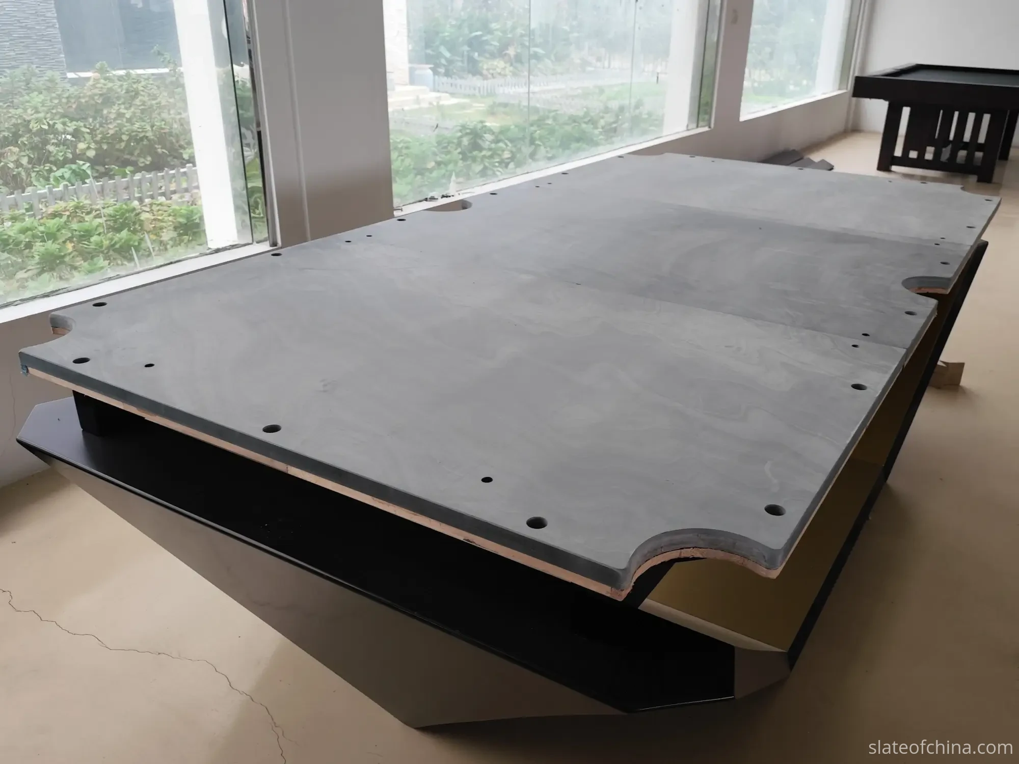
If the drawing does not make the joint relationship clear, we ask. A pocket that crosses a joint is not a problem, but it is a decision — and like every other decision on this page, it has to be made on the review bench, not at the machine.
Drawing Confirmation Checklist
Before machining begins, the drawing should be confirmed against the following items. This is not a questionnaire for us — it is a checklist for both sides, because the customer knows things about the table that we do not, and we know things about the slate that the customer does not. The list focuses on the pocket drawing review; the full slate specification is covered in the technical specifications page.
| Drawing Item | What the Manufacturer Should Confirm |
|---|---|
| Table type | Pool, snooker, Chinese 8-ball, or other |
| Overall slate size | Length × width of finished slate, each piece |
| Playing area | Finished playing-surface dimensions |
| Slate thickness | Nominal and finished thickness |
| Pocket opening | Opening dimensions and tolerance |
| Pocket profile | Radius, angle, curve or special geometry |
| Pocket location | Coordinates from agreed reference points |
| Pocket depth | Where applicable — recess or underside requirement |
| Corner vs side pockets | Correctly distinguished on the drawing |
| Joint positions | For multi-piece slate — does any pocket cross a joint? |
| Mounting holes | Diameter, position and spacing |
| Countersinks | Diameter and depth |
| Edge profile | Chamfer, radius or special edge requirement |
| Tolerance | Dimensional tolerance where required |
| Drawing revision | Which version controls production |
This checklist is particularly useful for OEM billiard slate and custom orders. For a repeat order with no changes, an existing approved drawing can serve as the reference — but it should still be identified as the current version, so that nobody accidentally switches to an older revision.
When There Is No Drawing at All
This is common, and it is not a problem — provided we handle it before production, not during it. Smaller table manufacturers, distributors, and customers modifying an existing table often do not have a CAD file. In that situation, we start with what is available: existing slate dimensions, a table model, photos, an old drawing, pocket measurements, rail dimensions, a pocket-liner sample, or a previous production specification. For a repeat order, an existing approved production drawing can be used as the reference directly.
If important dimensions remain uncertain, we clarify them before CNC machining. The pocket opening machining page covers the three routes we use when a drawing is not available — an existing sample, a physical template, or reverse engineering from measurements. In every case the route ends the same way: the geometry is captured in a confirmed drawing before the tool moves.
A few minutes spent confirming a dimension can save a complete slate set from being machined incorrectly. The cut is irreversible; the drawing is not.
Why OEM Pocket Cuts Live by the Drawing
For standard slate sizes, many dimensions may already be familiar to an experienced manufacturer — the technical specifications of common table types are well established, and a repeat order for a known model may need very little new confirmation. But OEM production is different, because OEM production is where the geometry stops being standard.
A table brand that needs its own pocket profile, its own mounting-hole pattern, customised slate dimensions, special pocket geometry, a special rail interface, or a modified playing area is not asking for a standard product. They are asking for a specific product, and the specificity has to be captured somewhere. The drawing is where it is captured. The drawing becomes the bridge between the table design and the slate manufacturing process — and if that bridge is incomplete, the slate that comes off the CNC is not the slate the customer designed.
This is why we encourage OEM customers to send their drawings before asking for a final machining quotation. A quotation based on a complete drawing is a quotation for a specific product. A quotation based on "standard pocket, 9 ft" is a quotation for an assumption, and assumptions are the most expensive thing in OEM billiard slate machining. The drawing is what turns a generic inquiry into a specific, quotable, machinable product.
The First Piece and the Drawing Agree
In our production process, once the drawing is confirmed and the CNC programme is written, the first piece off the machine is checked against the drawing — not against the operator's judgement, and not against a previous piece, but against the approved drawing itself. This is the last link in the evidence chain: the dimension had a source, the source was written down, the writing was reviewed, the review was approved, and the cut was made. The first piece is where we verify that the chain held.
The check covers the pocket opening dimensions, the pocket positions, the corner radii, the edge condition, and — for a multi-piece slate — the alignment of any cross-joint pocket halves. If the first piece agrees with the drawing, production continues. If it does not, production stops, because the error is cheaper to find now than at assembly, and far cheaper than at the customer's table.
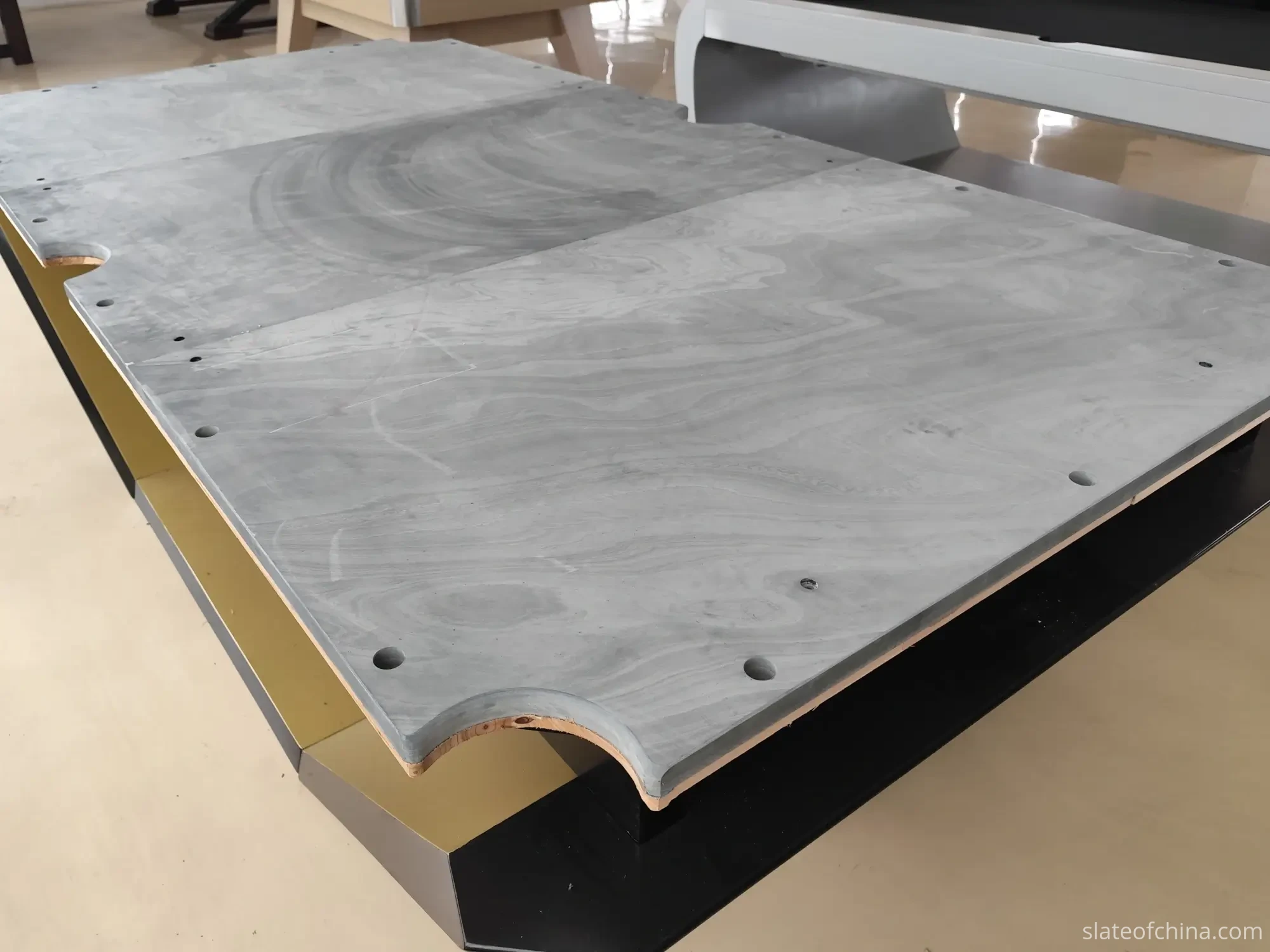
The first-piece check is not an inspection of the whole order. It is a verification that the drawing and the machine agree, made on the first piece, before the rest of the order is machined to the same programme. The full inspection process — and what buyers should check on their side — is covered in the quality control page; the point here is that the evidence chain does not end at the drawing. It ends when the first piece proves the chain held.
A Pocket Drawing Checklist Before the Tool Moves
Before a billiard slate order is released to CNC pocket machining, the following questions should have clear answers. If any of them is open, the drawing is not yet ready.
Slate. Are the overall dimensions correct? Is the thickness correct? Is the number of pieces correct? Is the playing area correct?
Pockets. Is the pocket opening dimension confirmed? Is the pocket shape confirmed? Are corner and side pockets correctly distinguished? Are the radii specified? Are all pocket positions confirmed from a datum?
Joint relationship. If the slate is multi-piece, does any pocket cross a joint? If so, is the cross-joint machining identified on the drawing?
Other machining. Are the mounting holes shown? Are threaded holes specified? Are countersinks required? Are there any special cuts?
Documentation. Is the latest drawing revision being used? Has the customer approved the final revision? Are all important dimensions legible? Are there any unresolved assumptions?
If those questions are answered before machining, the risk of an expensive pocket-cutting mistake is greatly reduced. If they are not, the risk is not reduced — it is merely deferred, and it will appear at the most expensive moment: assembly.
For standard production, an established specification may be enough. For OEM and custom billiard slate, a confirmed drawing — CAD, dimensioned PDF, or approved sample with a reverse-engineered drawing — is the safest starting point. Send the drawing first. Confirm the dimensions. Then cut the slate. That sequence helps both sides avoid unnecessary rework, and it ensures that the finished CNC machined billiard slate is made for the table it was actually intended to fit.
Frequently Asked Questions
Why do you need a drawing for billiard slate pocket cuts?
Because a pocket cut is a specific geometry machined into a specific panel for a specific table, and the geometry cannot be guessed from a table name. The pocket opening, shape, corner radius, centre position and relationship to the slate edge all have to come from a source — and the source has to be written down. A drawing that says "standard pocket" is a request, not a specification. The drawing is what turns a request into a dimension the CNC machine can cut.
Is "9 ft pool table" enough information to machine pockets?
No. A 9 ft pool table is a category, not a machining specification. Two 9 ft pool tables from different manufacturers can have different pocket openings, different corner radii, different pocket-centre positions and different relationships between the pocket and the slate edge. The drawing — not the table name — is the document the CNC programme follows.
What if I don't have a CAD drawing?
A CAD file is the best option, but it is not mandatory. We can also work from a dimensioned PDF technical drawing, an approved sample, a physical template, or detailed measurements. The key is that the geometry has to come from somewhere — it cannot be invented. If important dimensions remain uncertain, we clarify them before CNC machining, not during it. A sketch can start the conversation, but before production the unclear points have to be confirmed in a more rigorous form.
Can a photo of the table be used as a pocket drawing?
A photo is useful reference material — it helps us understand the table design, the cushion profile and the general pocket style — but it does not provide reliable dimensional information. Perspective distortion makes a pocket appear larger or smaller than it actually is, and there is no way to read a dimension from a photograph without a known reference scale in the same plane. We treat photos as reference, not as a production drawing.
What is drawing revision control and why does it matter for pocket cuts?
Revision control means that one identified version of the drawing — the final approved version — is used as the production reference, and every earlier version is superseded. It matters because one of the most common causes of custom machining errors is not a wrong dimension but a right dimension machined from the wrong version of the drawing. The production drawing should carry a revision identifier, a date and an approval mark, so that anyone who picks it up can see that it is the confirmed version.
How do you confirm a pocket drawing for a multi-piece slate?
For a multi-piece slate, we check whether any pocket crosses a joint between two pieces, because a cross-joint pocket has to be cut in two sections that meet exactly at the joint line. The two pieces are machined as a matched set, and the set is trial-assembled at the factory before packing to verify that the pocket halves align. The drawing has to make the joint relationship clear; if it does not, we ask before machining.
What happens if the pocket is machined from the wrong drawing version?
The pocket may look correct but fail to match the component it was cut for — the cushion, the liner, the rail bracket or the table cabinet. The error is usually not visible at the CNC machine; it appears at assembly, when the slate meets the rest of the table, and by then the pocket geometry cannot be uncut. The correction is either a rework or a remake, and the cost has multiplied by the number of components built around the assumption that the slate would be correct. This is why one approved drawing — not five email versions — is the production reference.
Related Reading
Send Us Your Pocket Drawing — We Will Confirm the Cut
If you are sourcing billiard slate with custom pocket cuts — whether for a new OEM model, a repeat production run, or a replacement slate for an existing table — send us your table drawing, an approved sample, or a dimensioned sketch. Before production, we can review:
- ✓Pocket opening dimensions and tolerances
- ✓Pocket shape and corner radii
- ✓Pocket centre positions from a defined datum
- ✓Corner vs side pocket geometry
- ✓Whether any pocket crosses a slate joint
- ✓Drawing revision and approval status
We can confirm whether the drawing provides enough information for CNC pocket machining — and flag any specification that needs clarification before the cutting tool moves.
Don't have a CAD drawing? Send us photos, measurements, an existing slate sample, or a pocket-liner sample. We can help establish the machining information before production. Start the conversation here.